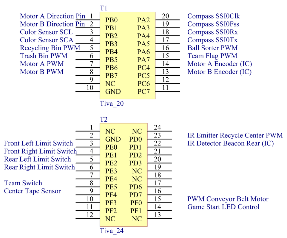
TIVA connectionsThe following connections were made to the TIVA Launchpad. Connections were prioritized depending on the alternate function needed for each pin. The alternate functions used are:
|
|
IR Detector Circuit
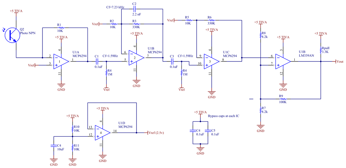
For detecting each beacon, it was decided that the robot must be able to locate a beacon from any position in the field, so it was important to design an IR receiver circuit with a high gain. The phototransistor was shielded using a piece of heat shrink to protect from unwanted interference. Two gain stages of 30:1 are implemented to correctly catch the signal from the beacon. Between the transresistive stage and the first gain stage, and between the two gain stages a high pass filter is inserted in order to reduce noise of ambient light. In the first gain stage, a low pass filter is inserted to reduce noise before amplifying the signal. At the end, a Schmidt trigger is implemented to guarantee a logic level signal.
|
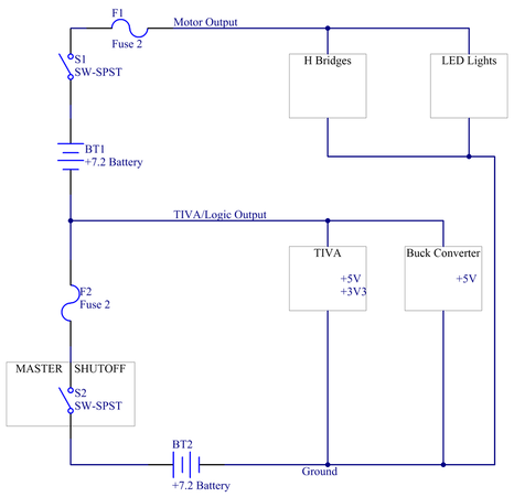
Power Distribution CircuitFor distributing power along the robot, two Ni-Cd batteries are used in series, with a switch and a 5A fuse between each battery. At the end of the first battery, two lines are taken out in order to feed the Tiva protection board and a buck converter. From the second battery the motors will be fed and the LED lights.
|
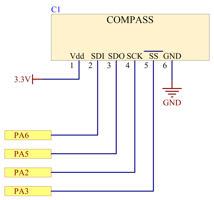
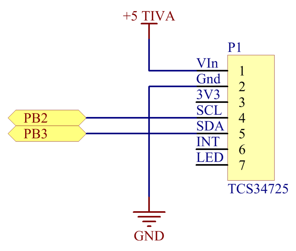
Compass & Color Sensor
Our Compass connection was made according to the specified datasheet, and programmed with a max frequency of 15 kHz.
For the color sensor, the SCL and SCA pins were connected to the PB2 and PB3 according to the instructions given in the color sensor code provided to us (I2C communication) |
|
|
|
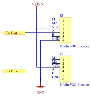
Magnetic encoderWe used a magnetic encoder to control the speed of the motors. The encoder was attached to the motor with a 3-D printed bracket. We selected the Pololu 3081 encoder and connected to the TIVA. The TIVA was programmed to use an input capture timer for detecting rising edges, in order to calculate the pulse width detected by the encoder. This was then used to back out motor RPM
|
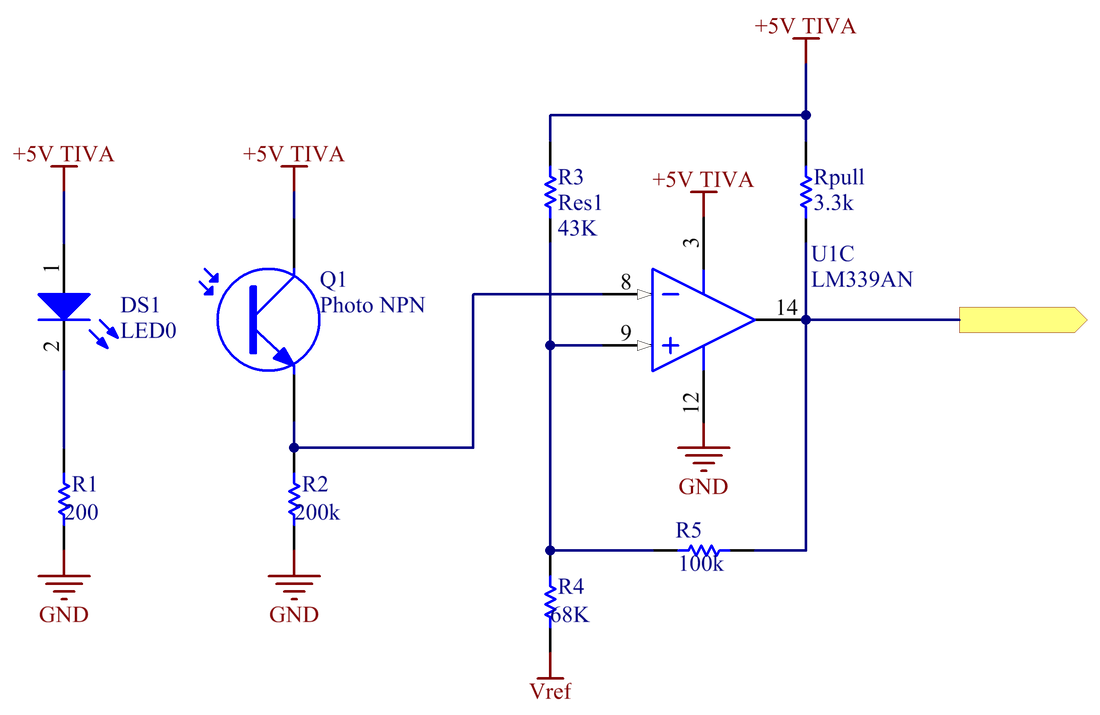
Tape SensorFor aiding navigation, a tape sensor was used in order to detect the tape line connecting the recycling centers . Since our strategy consisted of using dead reckoning to align with the beacon, only one tape sensor was used. In order to obtain a digital signal a Schmidt trigger was used for the output. Debouncing was added in software in order to reduce false positives while driving through the map.
|
|
|
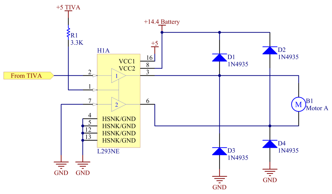
Conveyor Belt ControlFor controlling the conveyor belt motor, an H-bridge in drive-brake mode was selected. Measuring the motor obtained for the conveyor belt, a stall current of 600 mA was measured, so in base with that, an L293 H-bridge was selected. The enable line was tied to power and one of the control pins was tied to ground. The other pin was taken to the TIVA, where a signal of 100% or 0% was sent to the L293.
|
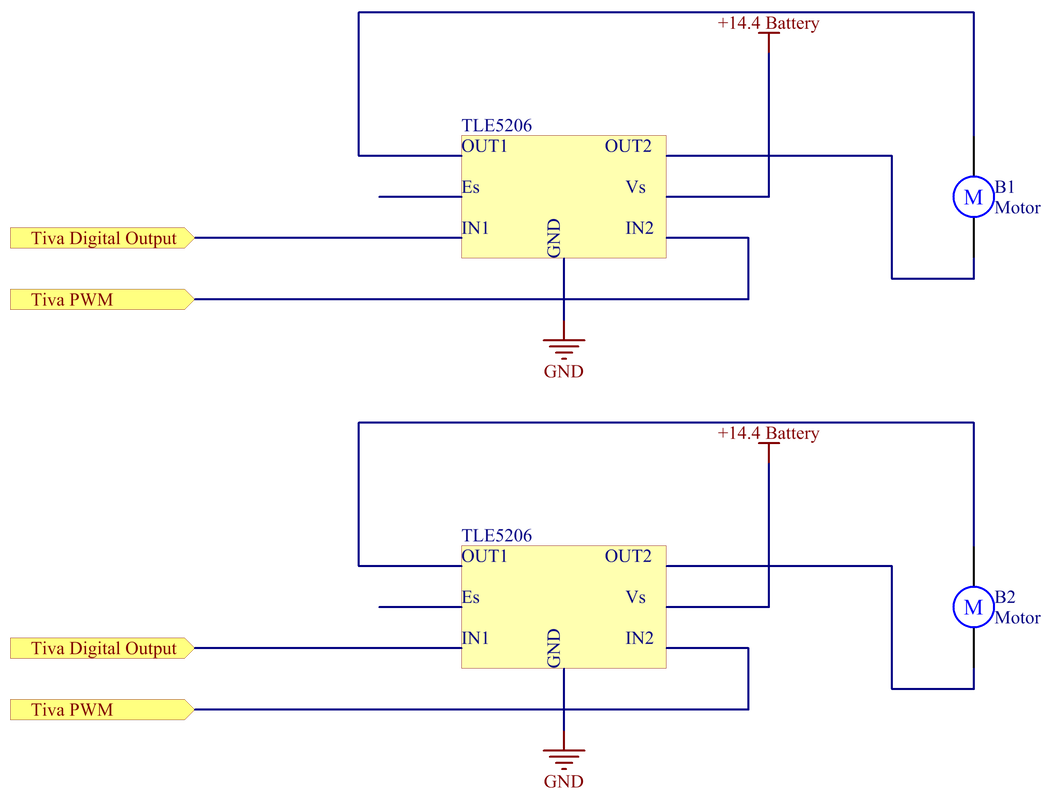
Drive train controlFor controlling the drive motors with a 14.4V signal, the TLE-5206 driver was selected for its capability of driving up to 5A of current. This exceeded the 2A stall current of the motors. Two pins were used to control each of the motor drivers. A digital output was used to set IN1 high or low depending on direction of rotation. IN2 was connected to the PWM signal from the TIVA. This pin controlled the speed of the motor. The motor was driven in drive-brake mode.
|
|
|
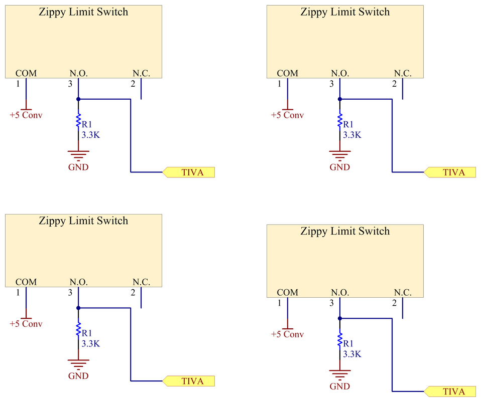
Limit SwitchesFor the Bumper limit switches, the 5V line was connected to the common terminal of each switch, and the Normally Open output was connected to the TIVA with a pull down resistor. This guaranteed that when the switch was not activated, the state would be a logical low. When depressed, the TIVA would read a logical high.
|
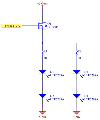
IR Emitter (Ray Blaster)For sending the IR signal to the recycling center, a P-type power MOSFET was used to control the output of the emitter, causing the signal to pulse when sending a PWM signal at the gate of the MOSFET. For maximum reach, four IR LEDs were put in a row together to increase the emitter angle. The PWM sent from the TIVA is sent at a 50% duty cycle. The PWM frequency was recycling center dependent.
|
|
|
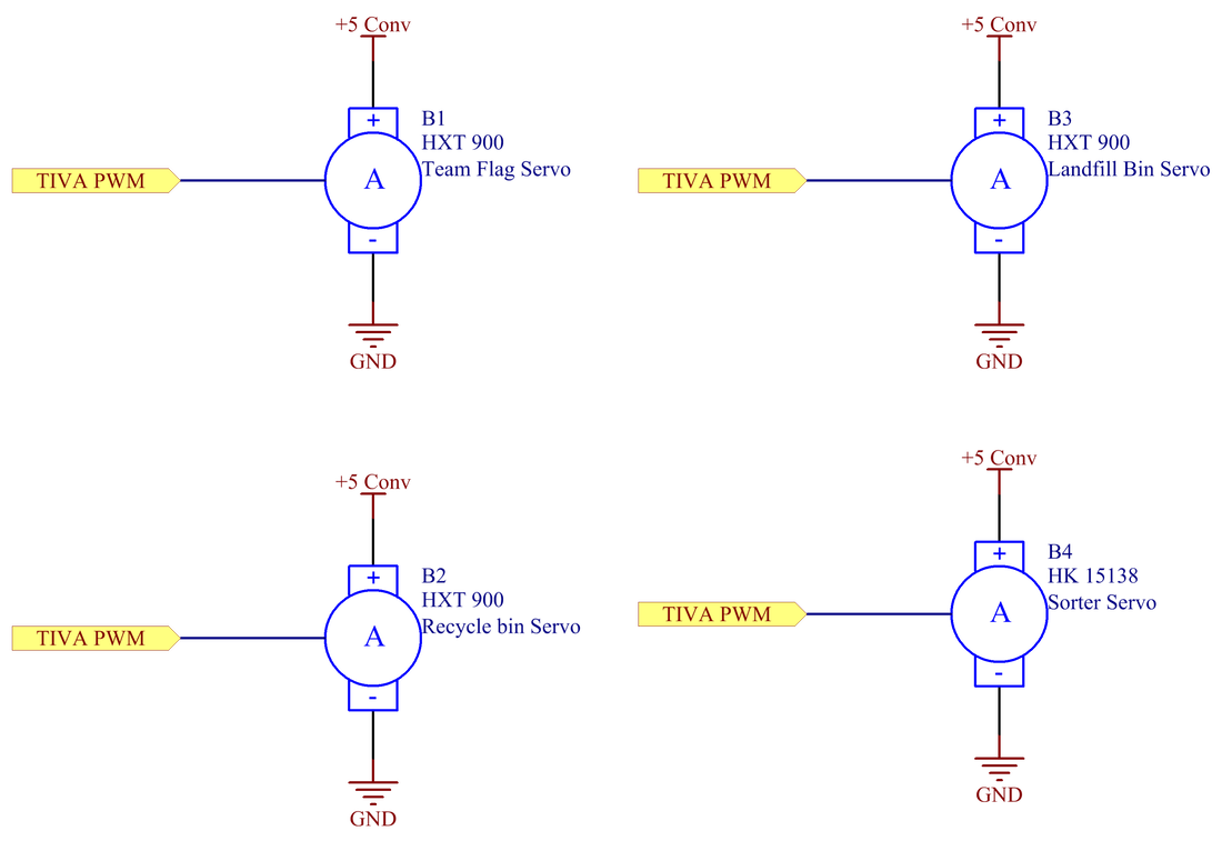
ServomotorsFor the final version of the robot, four different servomotors were used, all controlled from the TIVA using a 50Hz signal. The HK15138 servo was used to move the sorter to three different positions (neutral, drop to recycling and drop to landfill). Two HXT900 servos were used for opening and closing the landfill and recycling containers. A final HXT900 servo was used to display an American or Mexican flag, depending on the team North/South status.
|
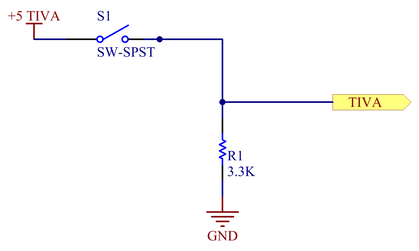
Team selection switchFor selecting between Team North and Team South, a SPST switch was used. This was connected to the TIVA such that when there was no connection, a pull down resistor forces a logical low for the input pin, and a logical high when a connection was established.
|
|
|
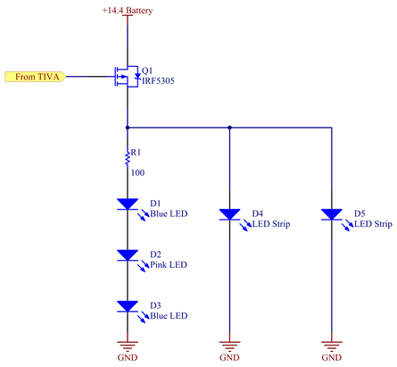
Lighting System ~Bling Bling~To indicate that a game has started, a combination of standalone LEDs and LED strips were used, all controlled using a P-type power MOSFET. The LEDs were connected to the
14.4 V power supply board. Using the MOSFET, the TIVA closed the circuit when the game began, and opened the circuit at the conclusion of the game. |
Download Schematics
| me218b_team_3.pdf |
